
Guide : DC DC converters precharge
Which precharge sequence for your DC DC converter ?
Definition
Precharge is the first step in each system starting up. Precharge consist in limiting the voltage supply into an electrical system via an auxiliary power supply circuit. Precharge hence allows a moderated power up with no damage risk for the electrical system components.
Context
Precharge is required when a voltage source is connected to the converter with a power switch in between and that source does not have a built-in precharge. Suddenly closing the switch will cause a current surge for a moment, damaging the converter and the devices connected to it.
To limit this phenomenon, a resistor must be engaged in parallel with the switch before the latter closes. The purpose of this operation is to increase the current gradually in the converter.
When the voltage across the resistor (therefore across the open switch) is less than 30V, the open switch can be closed without risk. When preloading needs to be done on the Low side and High side, preload the high side first. Even when the converter is not turned on (CAN off), if voltage is applied to its terminals (low and high side), damage can be caused. It is therefore necessary to preload the converter even when it is switched off.
Tame-Power contribution
Aware of the importance of the precharge of a powered up system, Tame-Power specially calculated precharges which are necessary to its DC DC converters. Moreover, Tame-Power HMI was specially designed to ensure support to precharge resistor dimensioning, in regard to the application system.
Precharge dimensioning
All Tame-Power DC DC converters need a precharge prior to their commissioning. According to devices which are connected to the DC DC converter electrical architecture, there are different specific cases impacting the precharge sizing:
- Electrical architectures already including a precharge system
- Electrical architectures needing a precharge system either in low side or high side
- Electrical architectures needing a precharge system in both low side and high side
Architectures including precharge systems for all devices
If all devices connected to the electrical architecture already have an integrated precharge system, it is not necessary to add a precharge system to the electrical architecture.
Architectures needing a precharge system in low side or in high side
When a precharge system is necessary either for low side or high side, a precharge system must be added to respective low side or high side terminals. Hence, only one additional precharge system is required.
Architectures needing a precharge system in low side and high side
Chen a precharge system is necessary for both low side and high side of the DC DC converter, it is necessary to provide two extra precharge systems for low side and high side terminals. Hence, two additional precharge systems are required.
When a precharge is needed in both low side and high side, it is mandatory to precharge the high side first.
Tame-Power solutions
Prechare procedure
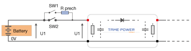
In order to limit damage risks for DC DC converters, Tame-Power developed a dedicated precharge sequence in reference to the layout above and as:
- Close the swith 1 (SW1) to precharge the system
- Check that the resistor terminals is lower than 30V
- If yes, close the switch 2 (SW 2)
- Possibly, open the switch 1 (SW 1 - optional)
Precharge calculation
| Voltage | R precharge |
|---|---|
| 50 | 5 |
| 100 | 10 |
| 150 | 15 |
| 200 | 20 |
| 250 | 25 |
| 300 | 30 |
| 350 | 35 |
| 400 | 40 |
| 450 | 45 |
| 500 | 50 |
| 550 | 55 |
| 600 | 60 |
| 650 | 65 |
| 700 | 70 |
| 750 | 75 |
| 800 | 80 |
| Voltage | R precharge |
|---|---|
| 50 | 3 |
| 100 | 5 |
| 150 | 8 |
| 200 | 10 |
| 250 | 13 |
| 300 | 15 |
| 350 | 18 |
| 400 | 20 |
| 450 | 23 |
| 500 | 25 |
| 550 | 28 |
| 600 | 30 |
| 650 | 33 |
| 700 | 35 |
| 750 | 38 |
| 800 | 40 |